BASIC ELECTRICAL FOR THE HVAC TECHNICIAN
Appendix A – Electrical Schematic Symbols
A reference guide to electrical symbols commonly encountered
in HVAC/R schematic and ladder diagrams.
Electrical schematics use symbols to represent components
and their electrical functions. Learning to recognize these
symbols allows you to read a schematic without needing to
know what each component physically looks like.
Use this appendix as a reference while reading schematics,
building circuits and troubleshooting HVAC/R electrical
systems.
How to Use This Appendix
A schematic symbol identifies the electrical function of
a component. It does not necessarily show the component’s
physical appearance.
Symbols are frequently accompanied by identifying labels.
For example, a relay coil may be identified as
C1, a switch as SW1,
or a lamp as B1. The symbol tells you
what type of component you are looking at while the label
identifies that particular component in the circuit.
Read the symbol for function, not appearance.
A relay, thermostat, transformer or contactor may look
very different from its schematic symbol. The schematic
is showing you how the component functions electrically
and how it connects to the rest of the circuit.
Important Rules for Reading Schematic Symbols
Switches and contacts are normally shown in their
normal or unoperated position.
Relay and contactor contacts are shown in the
position they have when the controlling coil
is de-energized.
Normally open (NO) contacts are open when the
controlling device is in its normal state.
Normally closed (NC) contacts are closed when the
controlling device is in its normal state.
Thermostatic and pressure controls are identified
by the condition that causes their contacts to
change state.
A schematic symbol represents electrical function,
not necessarily the physical appearance or physical
location of the component.
QUICK REFERENCE
Electrical Schematic Symbol Reference
The following reference sheet contains electrical symbols
commonly encountered in heating, air conditioning and
refrigeration equipment.
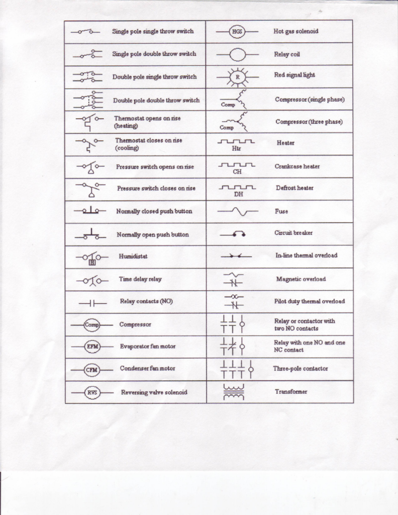
Electrical Schematic Symbol Reference.
Switches and Automatic Controls
Switches control whether an electrical path is open or
complete. Some switches are operated manually while others
respond automatically to temperature, pressure, humidity,
time or another condition.
Single Pole, Single Throw
Single Pole, Double Throw
Double Pole, Single Throw
Double Pole, Double Throw
Closes on temperature decrease
Closes on temperature increase
Opens on pressure rise
Closes on pressure rise
Closes when operated
Opens when operated
Humidity-actuated control
Changes state after a time interval
Relays and Contactors
Relays and contactors use an electrically operated coil to
change the position of one or more sets of contacts.
The coil and contacts may appear in different locations on
a ladder diagram even though they are physically part of
the same device. Matching identification labels tell you
which contacts are controlled by which coil.
Electromagnetic load that operates relay contacts
Open when the controlling coil is de-energized
Closed when the controlling coil is de-energized
Electromagnetic coil used to operate power contacts
Contacts used to control power to a load
Commonly used to control three-phase loads
Remember the definition of normal.
For a relay or contactor,
normal means the coil is de-energized.
A normally open contact is therefore open with the
coil de-energized. A normally closed contact is closed
with the coil de-energized.
Loads and Controlled Devices
Loads use electrical energy to perform work. HVAC/R
schematics contain many different load symbols depending
upon the equipment being controlled.
Provides visual indication
Single-phase compressor motor
Three-phase compressor motor
Moves air across the evaporator
Moves air across the condenser
Operates a heat-pump reversing valve
Operates a refrigerant solenoid valve
Converts electrical energy into heat
Provides heat to the compressor crankcase
Provides heat during electric defrost
Electrical Protection
Protective devices open a circuit when electrical or
temperature conditions exceed their intended limits.
The technician should understand what condition causes
each protective device to operate.
Opens the circuit when current exceeds the fuse’s
operating characteristics
Opens a circuit under specified overcurrent
conditions and can normally be reset
Temperature-responsive motor protection
Current-responsive protective device
Opens a control circuit in response to an
overload condition
Transformer
A transformer transfers electrical energy from one circuit
to another through electromagnetic induction.
In the control circuits studied in this course, a transformer
is commonly used to reduce line voltage to a lower control
voltage.
Primary
The primary winding is connected to the electrical
source supplying the transformer.
Secondary
The secondary winding becomes the
power source for the secondary circuit.
The transformer secondary is a source, not a load.
Once voltage is induced in the secondary winding,
that winding supplies electrical energy to the
secondary control circuit.
Reading Symbols as a Circuit
Recognizing individual symbols is only the first step.
Troubleshooting requires understanding how those symbols
work together as a complete circuit.
Where does the electrical energy originate?
→
What controls whether the circuit is complete?
→
How does current travel through the circuit?
→
What component uses the electrical energy?
When reading a schematic, identify these four functions
before trying to determine why the circuit does or does
not operate.
Sources and References
Non-Print Sources
Survey – Service Round Table Mailing List –
What do you look for in technicians?
June 20, 2006.
Print Sources
Althouse, Turgquist, Bracciano.
Modern Refrigeration and Air Conditioning.
Goodhart-WillCox Company, Inc.: Illinois, 1992.
RSES Technical Institute.
Reference Manual – A Guide for NATE Certification.
Refrigeration Service Engineers Society: Illinois, 2002.
Smith, Russell E.
Electricity for Refrigeration, Heating, and Air Conditioning.
Thomas: New York, 2003.
Whitman, William C., Johnson, William M.
Refrigeration & Air Conditioning Technology.
Delmar Publishers: North Carolina, 2005.