BASIC ELECTRICAL FOR THE HVAC TECHNICIAN
13. Thermostats
Temperature-operated switches used to control heating,
cooling and refrigeration equipment.
The thermostat is one of the parts of a heating and air
conditioning system most familiar to the customer. It provides
the point where the customer or end user selects the desired
temperature and operating mode.
Electrically, a basic thermostat can be understood as a
temperature-actuated switch. Instead of being
operated by your hand, its switching action is caused by a
change in temperature.
What You Should Learn
By the end of this lesson you should be able to:
Explain the basic purpose of a thermostat.
Distinguish between heating and cooling thermostat action.
Recognize heating and cooling thermostat schematic symbols.
Describe bi-metal, remote-bulb and solid-state
temperature sensing.
Explain the thermostat’s function in a basic
24 VAC control circuit.
Apply the Source → Switch → Path → Load method
when troubleshooting a thermostat circuit.
What Is a Thermostat?
A thermostat is a temperature-actuated control. It senses
temperature and causes a control action when the temperature
reaches or moves beyond a predetermined value.
That action may open or close electrical contacts or cause
an electronic control system to respond.
Think of a basic thermostat as a switch.
The switches used in earlier lessons were operated by hand.
A thermostat performs a similar electrical function, but
temperature causes the switching action.
Thermostatic controls may be used in line-voltage circuits,
low-voltage control circuits, or electronic control systems.
The technician must know what type of circuit is being serviced
before testing or replacing the thermostat.
Heating and Cooling Thermostat Action
For the circuits studied in this lesson, thermostatic
controls can be divided into two basic operating actions.
HEATING
Heating Thermostat
A heating thermostat
closes its contacts on a decrease in temperature.
If the thermostat is set for 72°F and the space
temperature falls below the control’s operating point,
the thermostat closes the heating circuit and calls
for heat.
COOLING
Cooling Thermostat
A cooling thermostat
closes its contacts on an increase in temperature.
If the space temperature rises above the control’s
operating point, the thermostat closes the cooling
circuit and calls for cooling.
| Control | Temperature Change | Control Action |
|---|---|---|
| Heating Thermostat | Temperature decreases | Contacts close — call for heat |
| Cooling Thermostat | Temperature increases | Contacts close — call for cooling |
Thermostat Schematic Symbols
Figures 25 and 26 show the schematic symbols for heating
and cooling thermostats. Notice that the temperature-actuated
portion of the symbol identifies the operating action of
the control.
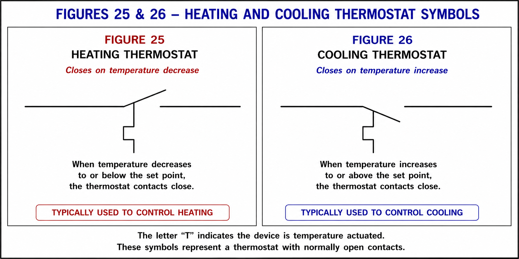
Heating and cooling thermostat schematic symbols.
Closes on temperature decrease.
Closes on temperature increase.
Thermostat Sensing Elements
A thermostat must have some method of detecting a
temperature change. The portion of the control that
responds to temperature is called the
sensing element.
Three types of sensing elements commonly encountered in
HVAC/R controls are:
Bi-metal sensing elements
Remote-bulb sensing elements
Solid-state temperature sensors
SENSING ELEMENT #1
Bi-Metal Sensing Elements
A bi-metal sensing element consists of two dissimilar metals
bonded together. Different metals expand and contract at
different rates as their temperature changes.
Because the two metals are mechanically joined, one cannot
expand independently of the other. The difference in expansion
causes the element to bend, twist or rotate.
→
→
→
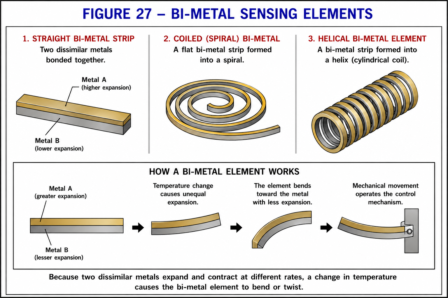
Examples of bi-metal temperature sensing elements.
The resulting mechanical movement can be used to operate
electrical contacts or another control mechanism.
SENSING ELEMENT #2
Remote-Bulb Sensing Elements
A remote-bulb temperature control uses a sensing bulb
connected to the control mechanism by a capillary tube.
The bulb, capillary and pressure-responsive portion of the
control form a sealed system containing a temperature-responsive
charge.
As the temperature of the sensing bulb changes, the pressure
within the sealed system changes. That pressure acts on a
diaphragm or bellows in the control.
Movement of the diaphragm or bellows is transferred through
a mechanical linkage to operate the electrical contacts.
→
→
→
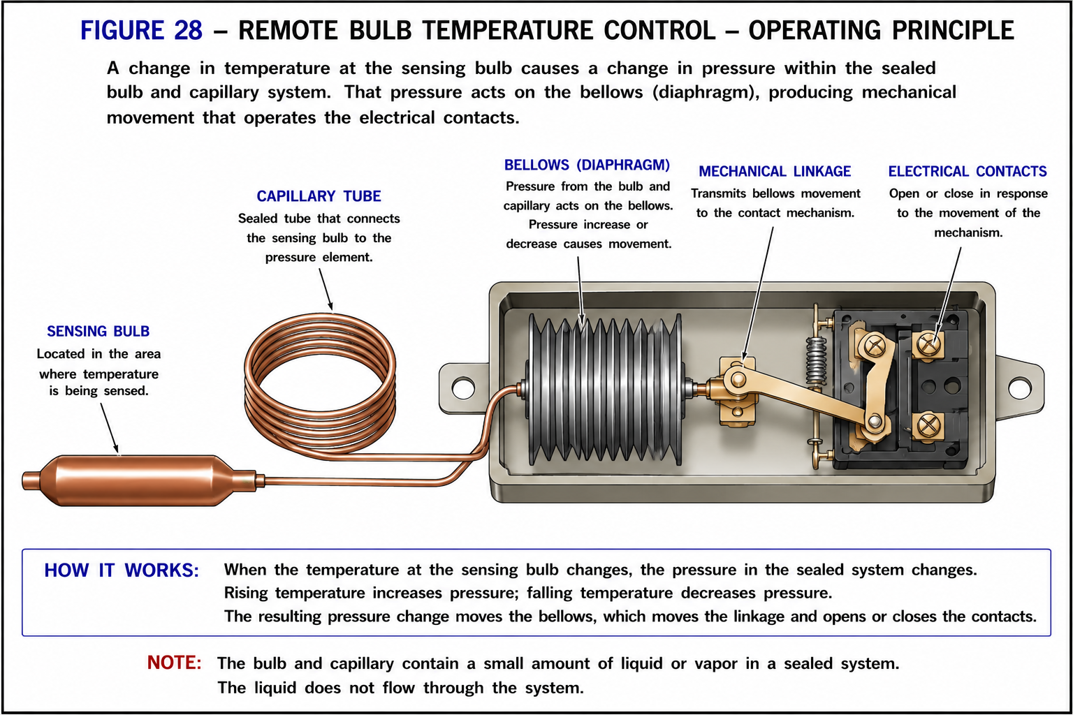
Remote-bulb thermostat operating principle.
The capillary tube is part of a sealed pressure system.
Do not think of the control simply as liquid traveling
through a tube. The important operating principle is the
change in pressure caused by a change
in sensing-bulb temperature.
Remote-bulb controls are commonly encountered in refrigeration,
hydronic systems and other applications where the sensing
location must be separated from the control mechanism and
electrical contacts.
Recognizing a Remote-Bulb Thermostat
Figure 29 shows a remote-bulb thermostat used in a window
air conditioner. This is an example of how the same operating
principle shown in Figure 28 appears in actual equipment.
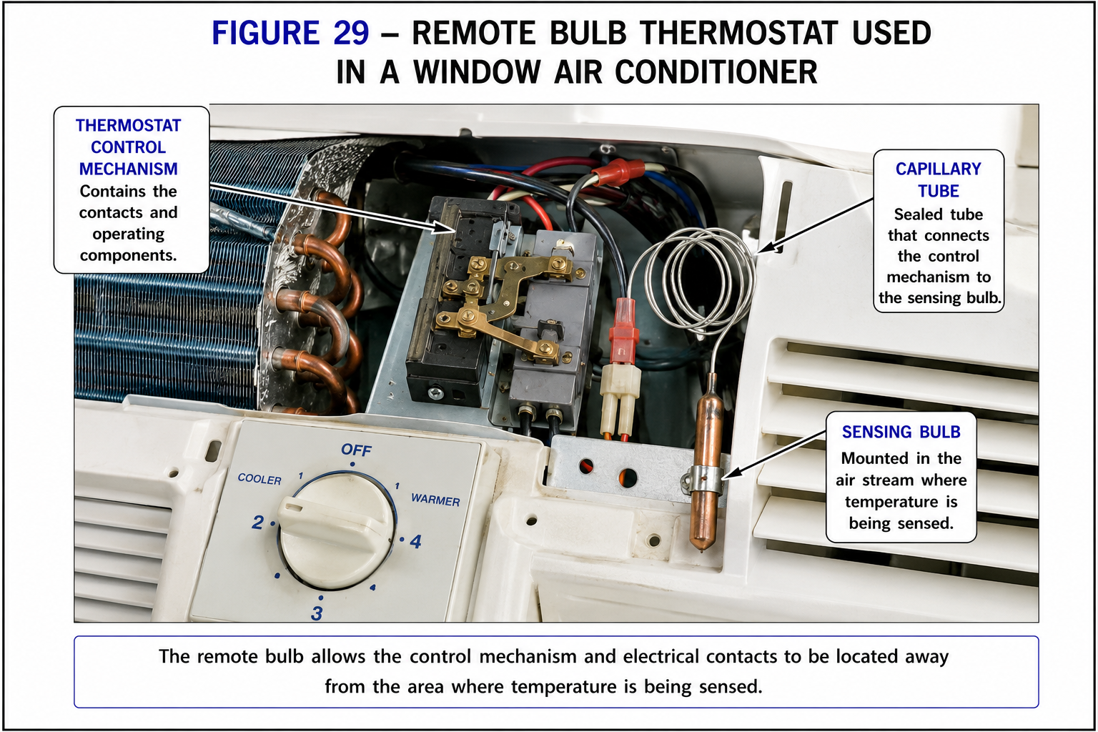
Remote-bulb thermostat used in a window air conditioner.
SENSING ELEMENT #3
Solid-State Temperature Sensors
Digital and electronic controls commonly use a solid-state
temperature sensor rather than a mechanical sensing element.
One common method uses a
thermistor — an electronic component whose
resistance changes predictably as its temperature changes.
→
→
→
Checking a Temperature Sensor
A solid-state temperature sensor can often be checked with
an ohmmeter when the manufacturer’s
resistance-versus-temperature information
is available.
1
Determine the Sensor Temperature
Measure or determine the approximate temperature
at the sensing element.
2
Isolate the Sensor
Follow the manufacturer’s procedure and disconnect
the sensor from the circuit when required for an
accurate resistance measurement.
3
Measure Resistance
Measure the resistance of the sensing element
with an ohmmeter.
4
Compare with Specifications
Compare the measured resistance with the
manufacturer’s specified resistance at that
temperature.
A resistance reading by itself is not enough.
You must know both the sensor temperature and the
manufacturer’s expected resistance at that temperature.
PUTTING THE LESSONS TOGETHER
The Thermostat in a 24 VAC Control Circuit
The previous transformer lesson established an important
electrical concept: the transformer secondary is the
power source for the secondary circuit.
The thermostat does not create that 24 VAC. Its job is to
control whether there is a complete electrical path from
the transformer secondary through the controlled load.
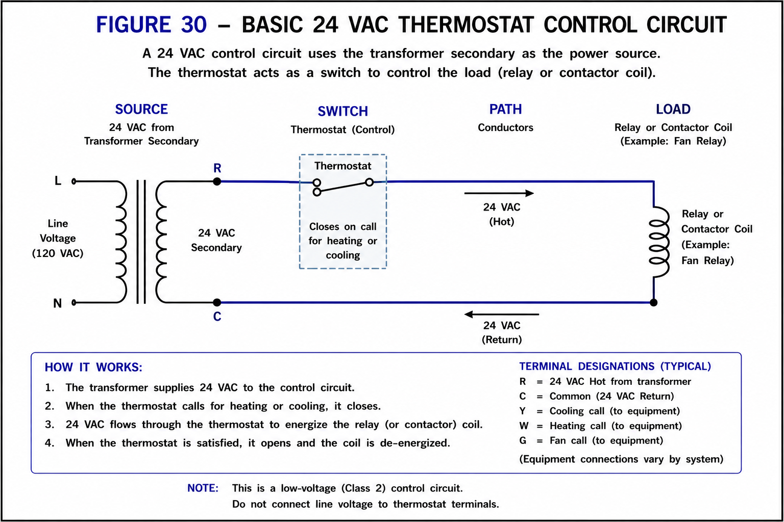
Basic thermostat control circuit.
Apply Source → Switch → Path → Load
The same troubleshooting method introduced earlier in this
course applies to a thermostat circuit.
The transformer secondary supplies the
low-voltage circuit.
The thermostat opens or closes in response
to temperature.
Conductors carry voltage between the source,
thermostat and load.
A relay, contactor, valve or other control device
uses the electrical energy.
Keep the roles separate.
Transformer secondary = Source
Thermostat = Switch
Relay or contactor coil = Load
Thermostat Wiring
Thermostat wiring varies with the equipment and the type
of control being used. Before testing, wiring or replacing
a thermostat, determine what type of circuit you are working on.
1
Determine the Circuit Voltage
Identify whether the thermostat is operating
in a line-voltage, low-voltage or electronic
control circuit.
2
Determine the Required Action
Identify whether the control must provide
heating action, cooling action, or multiple
control functions.
3
Use the Equipment Schematic
Follow the wiring diagram supplied with the
equipment. Do not assume terminal functions
based only on wire color.
4
Verify the Replacement
When replacing a thermostat or temperature
control, verify its voltage rating, operating
action and electrical characteristics.
Troubleshooting Thermostat Circuits
Do not begin troubleshooting by automatically replacing
the thermostat. Determine what the circuit should be doing
and then use the schematic and meter readings to locate
the problem.
Is the proper source voltage available?
Should the thermostat contacts currently be
open or closed?
Is voltage reaching the thermostat?
Is the thermostat passing voltage when it
should be closed?
Is there a complete path from the thermostat
to the load?
Is the controlled load itself operating properly?
What You Should Remember
A thermostat is a temperature-actuated control.
A heating thermostat closes on a decrease
in temperature.
A cooling thermostat closes on an increase
in temperature.
A bi-metal element moves because dissimilar
metals expand at different rates.
A remote-bulb control responds to pressure
changes within a sealed sensing system.
A solid-state temperature sensor can change
resistance as its temperature changes.
The transformer secondary is the source in
a basic 24 VAC thermostat circuit.
Always use the equipment schematic when
troubleshooting thermostat wiring.
Glossary of Terms
A temperature-actuated control used to cause an
electrical or electronic control action.
The portion of a temperature control that responds
to a change in temperature.
Two dissimilar metals bonded together so that
differences in thermal expansion produce movement.
A temperature-sensing bulb connected by a capillary
tube to a pressure-responsive control mechanism.
The small tube connecting a remote sensing bulb
to its control mechanism as part of a sealed system.
An electronic sensing element whose electrical
characteristics change with temperature.
A temperature-sensitive resistor whose resistance
changes predictably with temperature.
Do not troubleshoot the thermostat in isolation.
A thermostat is one component in a complete electrical
circuit. When equipment does not operate, determine the
source, the switching condition, the electrical path and
the load before deciding which component has failed.